Difference between revisions of "Laser Rotary Attachment"
Jump to navigation
Jump to search
(Created page with "= Purpose = The rotary tool for the Rabbit (80W) laser allows for the cutting/engraving of roughly cylindrical objects such as beer glasses, tubes, flashlights, etc. There are...") |
Neil.gabriel (talk | contribs) |
||
| (38 intermediate revisions by 3 users not shown) | |||
| Line 1: | Line 1: | ||
= Purpose = | = Purpose = | ||
| − | The rotary tool for the Rabbit (80W) laser allows for the cutting/engraving of roughly cylindrical objects such as beer glasses, tubes, flashlights, etc. There are actually two rotary tools, one with a drill-like chuck, and one with roller wheels on which the object to be marked rests. This tutorial is for the latter. | + | (UNDER REVIEW) The rotary tool for the Rabbit (80W) laser allows for the cutting/engraving of roughly cylindrical objects such as beer glasses, tubes, flashlights, etc. There are actually two rotary tools, one with a drill-like chuck, and one with roller wheels on which the object to be marked rests. This tutorial is for the latter. |
| − | [[File:RotaryJig.png|600px]] | + | [[File:RotaryJig.png|600px]] [[File:EtchedResult.png|326px]] |
| − | |||
| − | [[File:EtchedResult.png| | ||
= Process = | = Process = | ||
| − | == Rotary Tool == | + | == Rotary Tool Setup == |
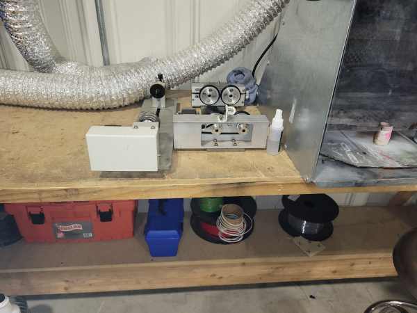
| − | + | # Locate the rotary tool next to the laser PC by the pay box. <br>[[File:Rotary_Storage.jpg|600px]] | |
| − | [[File: | + | # Turn on the laser, and lower the bed 6 inches or so. '''Taking care to ensure''' that there is nothing below the bed that will be in the way of this movement. |
| − | + | # Place the rotary tool on the honeycomb with the motor end to the right. Square up the tool using the honeycomb holes.<br>[[File:Rotary_Tool_7.jpg|600px]] | |
| − | + | # Locate the Rotary Tool cable (red arrows in picture above) in the front right inside corner of the laser and plug it into the motor of the Rotary Tool.<br>[[File:Rotary_Tool_8.jpg|600px]] | |
| − | + | # Using the control panel arrow buttons, move the laser in the Y axis until it is directly over the center of the bolt head on the left support wheel assembly and press the ORIGIN button on the control panel.<br> | |
| − | + | #* After you perform the following steps, you will not be able to move the gantry in the Y-axis using the control panel up and down buttons, so get it where you want it now. | |
| − | + | # '''TURN OFF THE LASER WITH THE KEY''' | |
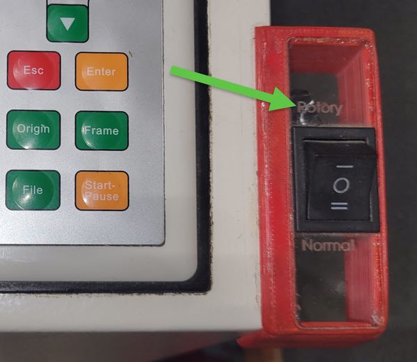
| − | + | # Place the Rotary/Normal rocker switch in the Rotary position. <br>[[File:Rotary_Switch.jpg|600px]] | |
| − | + | # Turn the laser back on. | |
| − | + | # Once the laser starts up, it will find the origin in the X-axis, but will not move in the Y-axis. The rotary drive wheels should instead spin. | |
| − | + | # When the laser is ready, you should be able to rotate the rotary wheels with the up and down buttons on the key pad. | |
| − | + | #* NOTE: The side of the rotary tool with the motor attached should be on the right side, otherwise the up/down buttons (and your artwork) will be backward. | |
| − | + | # Now we want to make sure that the travel in the Y/rotary axis is correct. | |
| − | + | ## Manually move the gantry back out of the way. It will move freely front to back since the Y motor is not on. If it does not freely move, re-check the switch position in step 7. | |
| − | + | ## Place your work piece on the rotary wheels. For objects with an open interior, open the clamp on the right side and place inside the work piece to hold it down on the driven wheels. Move the left wheel assembly up to the left end of the work piece and tighten the thumb wheel. <br>[[File:Rotary_Tool_3.jpg|600px]] | |
| − | + | ##* NOTE: for cylinders that don't have an open end, the clamp can be moved by removing the bolt in the lever and rotating to the side.<br>[[File:Rotary_Tool_4.jpg|600px]] | |
| − | + | ## Jog forward and backward with the up and down arrow on the key pad, to make sure the material doesn't "walk" to the left, and off the wheels. | |
| − | + | ## The left (non-driven) set of wheels can be raised/lowered via the wheel in the back (level the work piece engrave area), and slide left/right by loosening the knob on the left.<br>[[File:Rotary_Tool_5.jpg|600px]] | |
| − | + | # Manually move the gantry over the center of the work piece and use the left/right arrows on the control panel to put the laser in the center of your engrave area. Use the control panel up/down arrows to center the logo if needed.<br>[[File:Rotary_Tool_6.jpg|600px]] | |
| − | + | #* NOTE: Lower the bed using the Z axis to ensure the laser clears the work piece. | |
| − | [[File: | + | # Press the "Z/U" button and navigate to "AUTOFOCUS" and press "ENTER". It is '''crucial''' that the probe contact your material or the laser head may impact the bed and compress the focal tube. If you are going to miss your material with the auto-focus probe use the "ESC" key to stop the auto-focus process, or use the emergency stop to prevent the crash. |
| − | + | # Once you have the laser centered and focused, press ORIGIN on the control panel. | |
| − | [[File: | + | # Press the “FILE” button to load the file to the laser cutter’s memory |
| − | + | # At this point "FRAME" can be used to physically outline the outer-bounds of the work area for your job. The laser head will travel in a rectangular pattern that represents the boundaries of your file. | |
| − | [[File: | + | # You are now ready to engrave! Press the “START” key to start the laser from your previously declared origin point. |
| − | + | # Monitor your job closely. If you want to inspect the quality of your engraves mid run you may do so by pressing the "Start-Pause" button. If you open the lid without pausing the run it will interrupt the beam but continue its motion. | |
| − | |||
| − | |||
| − | |||
| − | == | + | == Lightburn Sofware Setup == |
| − | 1 | + | A short LightBurn tutorial part 1 [[Media:Laser_Rotary_in_Lightburn_1.pdf|is available here.]]<br /> |
| − | + | Part 2 [[Media:Laser_Rotary_in_Lightburn_2.pdf|is available here.]]<br /> | |
| − | |||
| − | [ | ||
| − | |||
| − | |||
| − | |||
| − | |||
| − | |||
| − | |||
| − | |||
| − | |||
| − | |||
| − | |||
| − | |||
| − | |||
| − | |||
| − | |||
| − | |||
| − | |||
| − | |||
| − | |||
| − | |||
| − | |||
| − | |||
== PUT IT BACK AS IT WAS == | == PUT IT BACK AS IT WAS == | ||
After etching/cutting your design, make sure to put everything back (both software and hardware) so the next person isn't confused. | After etching/cutting your design, make sure to put everything back (both software and hardware) so the next person isn't confused. | ||
| − | + | # Disconnect the Rotary cable on the motor and return it to the front inside of the laser. | |
| − | + | # Place the Rotary/Normal rocker switch in the Normal position. <br>[[File:Rotary_Switch.jpg|600px]] | |
| − | + | # Return the Rotary Unit to its storage location | |
| − | + | # Raise the bed, test that both X and Y-axes move as expected and move to the right rear corner. Press ORIGIN to save the zero location. | |
| − | |||
| − | |||
| − | |||
Latest revision as of 19:35, 18 March 2025
Contents
Purpose[edit]
(UNDER REVIEW) The rotary tool for the Rabbit (80W) laser allows for the cutting/engraving of roughly cylindrical objects such as beer glasses, tubes, flashlights, etc. There are actually two rotary tools, one with a drill-like chuck, and one with roller wheels on which the object to be marked rests. This tutorial is for the latter.


Process[edit]
Rotary Tool Setup[edit]
- Locate the rotary tool next to the laser PC by the pay box.
- Turn on the laser, and lower the bed 6 inches or so. Taking care to ensure that there is nothing below the bed that will be in the way of this movement.
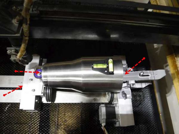
- Place the rotary tool on the honeycomb with the motor end to the right. Square up the tool using the honeycomb holes.
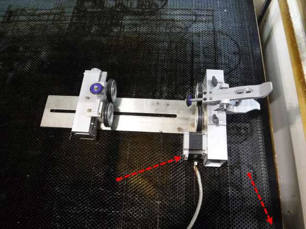
- Locate the Rotary Tool cable (red arrows in picture above) in the front right inside corner of the laser and plug it into the motor of the Rotary Tool.
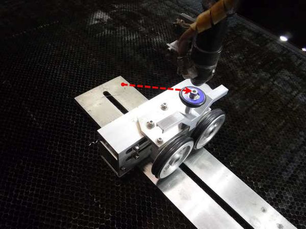
- Using the control panel arrow buttons, move the laser in the Y axis until it is directly over the center of the bolt head on the left support wheel assembly and press the ORIGIN button on the control panel.
- After you perform the following steps, you will not be able to move the gantry in the Y-axis using the control panel up and down buttons, so get it where you want it now.
- TURN OFF THE LASER WITH THE KEY
- Place the Rotary/Normal rocker switch in the Rotary position.
- Turn the laser back on.
- Once the laser starts up, it will find the origin in the X-axis, but will not move in the Y-axis. The rotary drive wheels should instead spin.
- When the laser is ready, you should be able to rotate the rotary wheels with the up and down buttons on the key pad.
- NOTE: The side of the rotary tool with the motor attached should be on the right side, otherwise the up/down buttons (and your artwork) will be backward.
- Now we want to make sure that the travel in the Y/rotary axis is correct.
- Manually move the gantry back out of the way. It will move freely front to back since the Y motor is not on. If it does not freely move, re-check the switch position in step 7.
- Place your work piece on the rotary wheels. For objects with an open interior, open the clamp on the right side and place inside the work piece to hold it down on the driven wheels. Move the left wheel assembly up to the left end of the work piece and tighten the thumb wheel.
- NOTE: for cylinders that don't have an open end, the clamp can be moved by removing the bolt in the lever and rotating to the side.
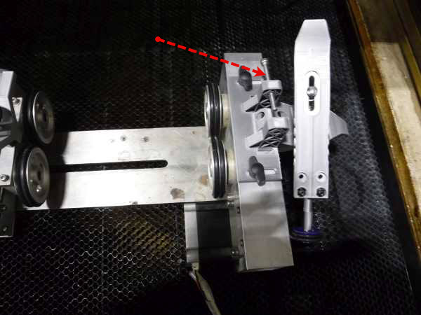
- NOTE: for cylinders that don't have an open end, the clamp can be moved by removing the bolt in the lever and rotating to the side.
- Jog forward and backward with the up and down arrow on the key pad, to make sure the material doesn't "walk" to the left, and off the wheels.
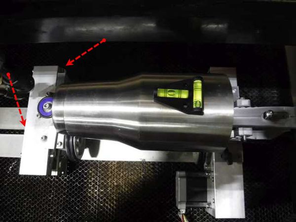
- The left (non-driven) set of wheels can be raised/lowered via the wheel in the back (level the work piece engrave area), and slide left/right by loosening the knob on the left.
- Manually move the gantry over the center of the work piece and use the left/right arrows on the control panel to put the laser in the center of your engrave area. Use the control panel up/down arrows to center the logo if needed.
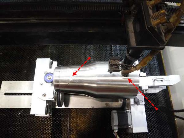
- NOTE: Lower the bed using the Z axis to ensure the laser clears the work piece.
- Press the "Z/U" button and navigate to "AUTOFOCUS" and press "ENTER". It is crucial that the probe contact your material or the laser head may impact the bed and compress the focal tube. If you are going to miss your material with the auto-focus probe use the "ESC" key to stop the auto-focus process, or use the emergency stop to prevent the crash.
- Once you have the laser centered and focused, press ORIGIN on the control panel.
- Press the “FILE” button to load the file to the laser cutter’s memory
- At this point "FRAME" can be used to physically outline the outer-bounds of the work area for your job. The laser head will travel in a rectangular pattern that represents the boundaries of your file.
- You are now ready to engrave! Press the “START” key to start the laser from your previously declared origin point.
- Monitor your job closely. If you want to inspect the quality of your engraves mid run you may do so by pressing the "Start-Pause" button. If you open the lid without pausing the run it will interrupt the beam but continue its motion.


Lightburn Sofware Setup[edit]
A short LightBurn tutorial part 1 is available here.
Part 2 is available here.
PUT IT BACK AS IT WAS[edit]
After etching/cutting your design, make sure to put everything back (both software and hardware) so the next person isn't confused.
- Disconnect the Rotary cable on the motor and return it to the front inside of the laser.
- Place the Rotary/Normal rocker switch in the Normal position.
- Return the Rotary Unit to its storage location
- Raise the bed, test that both X and Y-axes move as expected and move to the right rear corner. Press ORIGIN to save the zero location.