ShopBot
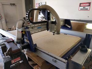
TinkerMill has a ShopBot PRS Alpha, a CNC router that can be used for cutting wood or plastic according to CAD designs. The usual workflow is to create a design in CAD or drawing software (such as Inkscape, CorelDraw, or Adobe Illustrator), load it into VCarve, which plans the cuts and outputs parts files, which are then loaded into the ShopBot software to execute on the machine.
Basics
The essentials of operating the ShopBot are below. They are here as a reference, and not a substitute for taking the ShopBot class.
Approved Materials
While the ShopBot is capable of cutting many different types of material, there are some limitations. Below is a list of the approved materials on the TinkerMill ShopBot
- Soft Wood
- Hard Wood
- MDF
- Chipboard
- Plywood
- Plastics (Use caution not to melt!)1
- Garolite (G10)/FR41
- Foam1
- Aluminum (drilling operations and thin sheet metal only)2
1: These materials may have health hazards associated with them. Please use proper techniques to prevent dust being spread in the woodshop. Talk with your instructor for suggestions.
2: Only with prior approval from the Executive Director (Ron Thomas) or the ShopBot Shop Captain (Matt Stallard). Contact them via Slack or email in advance for approval.
Safety
The typical and obvious woodshop safety precautions should also be used with the ShopBot: always wear safety glasses; keep your hands away; do not wear baggy sleeves, jewelry, etc. that might get caught. More specific to the ShopBot:
- Do not leave the ShopBot running unattended. Hitting the space bar will pause a cut and allow it to be resumed.
- Beware of the tracks that the x-axis carriage travels on. Do not rest your hands on them. The carriage can move quickly and crush fingers.
- Be sure your work is securely mounted on the table in all three dimensions (see Securing your work).
- Use adequate tabs for any profile cuts. Although there's no one tab size that works for any project, bigger tabs are always safer.
Starting the ShopBot
Scan your badge on the TinkerAccess terminal to log in. Turn the big red switch on the ShopBot to turn it on.
If the computer is not logged in, the password is "password". On the computer, start the ShopBot 3 program. Make sure all the emergency stops are not pushed. When the software starts up, you will need to push the blue reset button.
Datum the X and Y axes by pressing the 'Home X,Y Axes' button on the control window. This will zero the X and Y axes to the bed.
Warming up the ShopBot
It is important to warm up the ShopBot before use, to protect an important (and expensive) bearing. To warm it up, start the spindle and leave it spinning for at least 20-30 minutes. A reasonable workflow is to start the spindle when you first start up the machine, and then let it go while you secure your work.
Set the RPM to 8,000 to start.
Then increase to 12,000 after about 10 minutes. 'Spindle RPM Control' is under 'Tools' on the command console.
To start the spindle, open the keypad control (hit K), and then toggle Output 1 on the Position (red) pane. Then, press the green Start button on the remote.
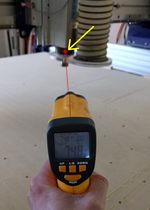
There is a temperature sensor attached to the ShopBot. Press the button and it will display current spindle temperature in degrees Celcius. Ideally the temperature should reach 33c. This temperature was agreed to for warm part of the year. As we get into winter the group should determine what a good Winter temperature should be.
Securing your work
It is important to secure your work to the ShopBot table in all three dimensions, so that it cannot slide, lift, or spin. There are several ways to do this:
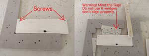
- Secure it to the spoilboard with screws. Be sure you use enough and that they sufficiently extend into the ShopBot table (about 1/4").
- If you cannot screw into your work, you can wedge it in place horizontally and clamp it down vertically, as show in the image to the left. (TODO: fix the wedges and take a new photo.)
It is also important that any pieces that may be cut free remain secure.
Changing bits
Safety note: be sure to close the keypad control before changing the bit. This ensures that it takes more than a single button press to start the tool.
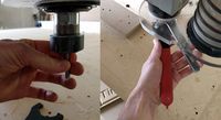
Snap the appropriately-sized collet into the collet nut. Before inserting the bit, align it with the ShopBot spindle and screw it in a few turns. Then, insert the bit and hold it while you hand-tighten the nut. Be sure the flutes are entirely exposed, so the collet has full contact with the bit (and no empty space). Carefully tighten the nut with the two wrenches. It's easiest to align the wrenches so they can just be squeezed together, although it takes some mental acrobatics to apply the right-hand rule upside-down and with a pair of wrenches.
Zeroing
Manually zero the X and Y axis to the origin of you material using the keypad and the Zero Axis button.
NOTE: If using the X&Y zero of the machine, make sure that your tool path does not cut into the wooden blocks on the board (ie the cutter goes slightly into the negative in the X or Y direction). These are zeroed and squared to the bed. If you damage these, you will be responsible for replacement and re-planing of the damaged blocks. Report this to the shop captain if this occurs.
Connect the Z zeroing plate to the connector on the Z axis. Test the Z zeroing plate's continuity by tapping the bottom of the bit to the plate. Input 1 should light up indicating proper continuity. Make sure that the plate is clean and will not shift position during the routine.
IMPORTANT! You should always zero to the bed when cutting through material. Make sure that your V carve file is set up with the Z zero at the bottom of your material. If you fail to zero this properly and end up cutting into the spoil board, you will be responsible for re-planing or replacement of the spoil board. Report this to the shop captain if this occurs.
Proceed to zero the Z axis using the 'Z zero' button on the control window.
Loading and running cuts
Once ready to run your tool path, click on 'File>PART FILE LOAD' and select the tool path you wish to run.
Ensure that you have the right file loaded, and press the green "Start" button on the control window. This will prompt you to start the spindle by manually pressing the green start button on the control pendant. Make sure that you press the start button on the control pendant before clicking 'OK' on the spindle start prompt. If 'OK' is pressed before the spindle is running, the gantry will begin moving and can break your bit and damage the machine.
Stay with the machine as it is running and keep an eye out for anything that does not seem right. Stop the machine if something does not seem right and investigate the cause.
VCarve and planning ShopBot cuts
So you have a beautiful drawing of your part, and you have a ShopBot, which can move a tool around in 3-dimensional space. How can you put the two together to cut your part out? The task of planning toolpaths--where the bit is going to move, and at what speed--is usually accomplished using VCarve. A trial edition is sufficient for planning cuts, and then you can save your work and load it on the full version at TinkerMill to calculate and export toolpaths, which are then loaded into the ShopBot software to be executed. TinkerMill has a MakerSpace license for VCarve Pro, which allows members to activate a home installation of VCarve as clients. The activation key is provided to those taking the ShopBot class.
Loading a drawing
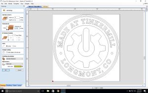
VCarve can read several drawing formats, including .ai and .dxf files. Choose "File > Open" and select the file. This example is done with Made at TinkerMill v1.ai. The Job Setup interface will appear. This is where you can adjust the size of the work, and define where the axes zeros will be. Tip: By default, the default work dimensions are a bounding box on the design. If you want the drawing centered on a slightly larger workpiece, input the new dimensions in the Job Size field, and then check and uncheck the "Scale design with job size" box.
Setting zeros is an important step, and you must be careful that the zero position you choose on the design matches the zeros you set on the machine when you go to cut. Zeroing to the bottom of the workpiece is a safe choice, because you can then zero the machine to the bed, and know that you won't cut through it. Note, however, that your choices here are not final--you can change the zero settings later.
Planning cuts
Profile
Speeds and Feeds Table
| Wood | |||||||
|---|---|---|---|---|---|---|---|
| Material | Bit Size and number of Flutes | Cutter Style | Speed (RPM) | Feed Rate (IPS) | Pass Depth | Notes | |
| MDF | 1/4" | 2 Flute | Upcut Straight | 18,000 | 4-5 | 0.125" | Pretty clean finish (Matt S) |
| 1/2" | 2 Flute | V Carve | 18,000 | 3-4 | 0.125" | Need to test this more (Matt S) | |
| Birch Plywood | 1/4" | 2 Flute | Upcut Straight | 18,000 | 2-3 | 0.125" | Not sure if the best feed and speed, some tearout (Matt S) |
| Birch Plywood | 1/4" | 2 Flute | Upcut Straight | 18,000 | 2.5 | 0.75" | Acceptable cut, could use some tuning. (Gordon R) |
| Plastics | |||||||
|---|---|---|---|---|---|---|---|
| Material | Bit Size and number of Flutes | Cutter Style | Speed (RPM) | Feed Rate (IPS) | Pass Depth | Notes | |
| Phenolic Resin Paper (1/8" thick) | 1/8" | 3 Flute | Upcut Straight | 12,000 | 0.83 in/sec | 0.125" | |
